
Understanding TCP/IP: Packets, Connections and Reliability
We use networks every day, but much of their behaviour stays out of sight. Follow a request from application bytes to packets to understand how TCP/IP makes communication work.
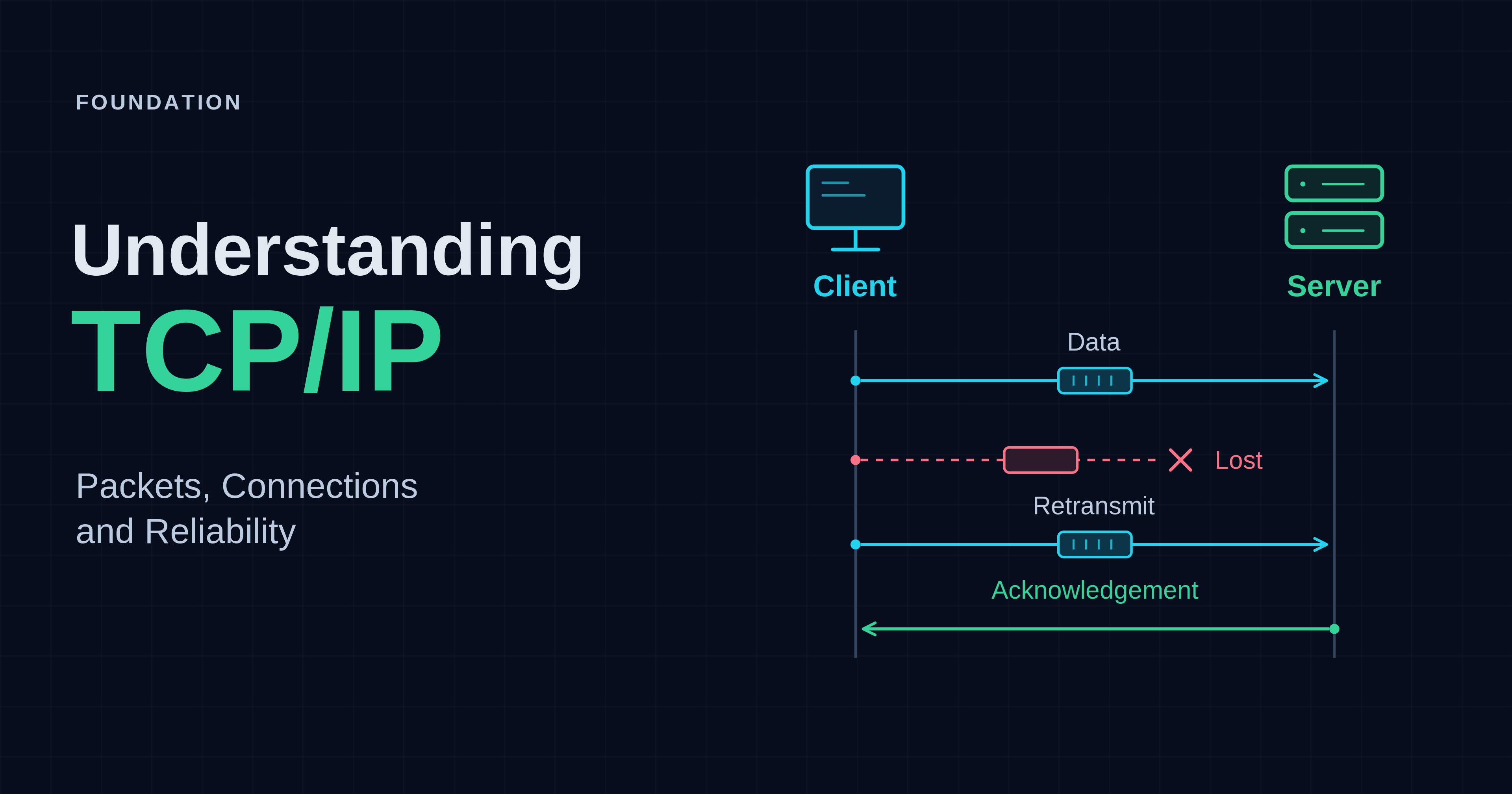
Computers need to exchange data even when they use different hardware, sit on different networks and encounter lost packets. TCP/IP separates those problems into manageable responsibilities. Following one request from an application to a server reveals how addressing, routing and reliable transport work together—and where their guarantees stop.
Opening a website, checking out a repository and calling an API all depend on mechanisms that are usually invisible when everything works. An application produces bytes. Somehow those bytes must reach the right application on another computer, across links with different capacities, packet sizes and failure modes. A fast connection is not enough: both ends also need to agree about what arrived, what is missing and whether either side can accept more.
That problem predates the web. ARPANET connected its first nodes in 1969, but interconnecting independently designed networks introduced a further challenge: how could they communicate without all adopting the same internal technology? Work on packet switching, open-network architecture and internetworking involved many researchers and institutions. Robert Kahn and Vinton Cerf's collaboration led to a published protocol design in 1974; the design evolved, and ARPANET's planned transition from NCP to TCP/IP took place on 1 January 1983.[1]
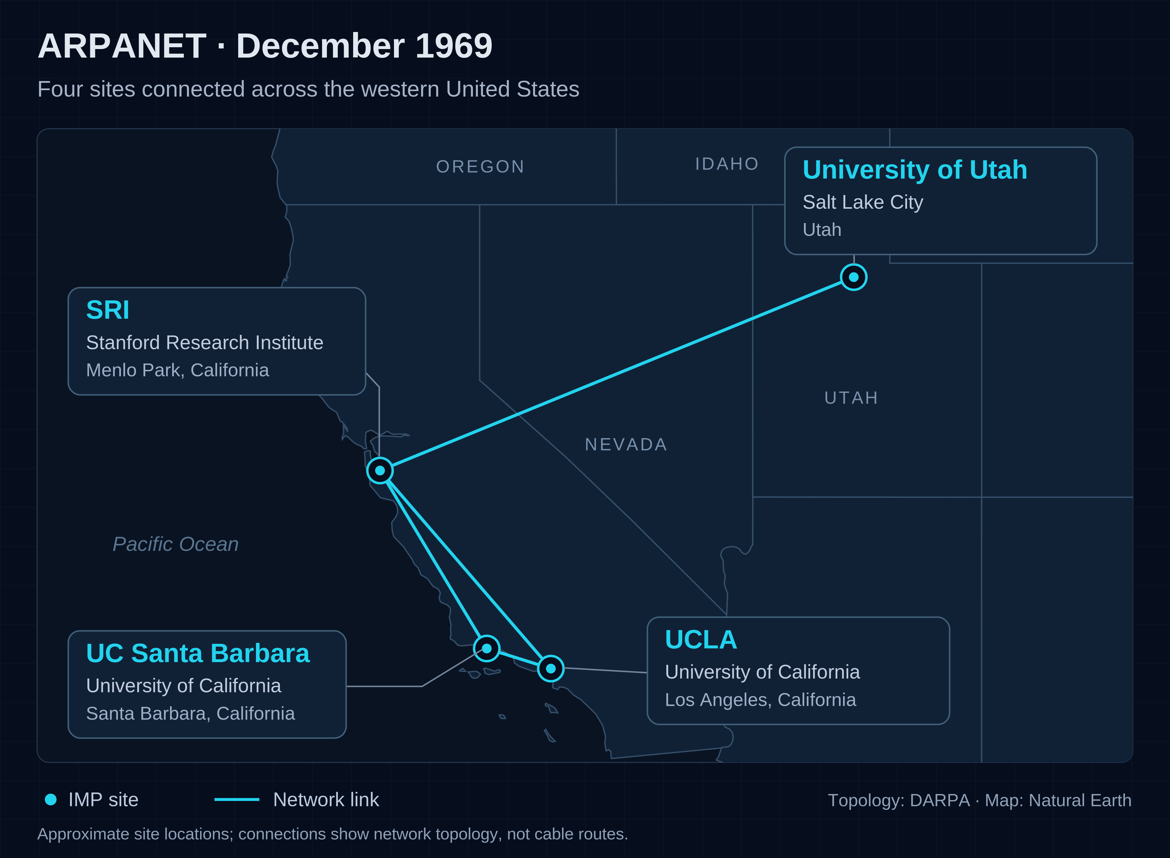
ARPANET in December 1969. Our visualization of the four-site network, based on DARPA’s historical diagram, with a Natural Earth basemap.
The enduring idea is separation. Networks can forward packets without understanding every application, while communicating endpoints can reconstruct a useful conversation from an imperfect packet service. This article develops that idea through one request, then uses a small real loopback experiment to make the application-facing behaviour visible.
In our Foundation series, we take a closer look at the technologies we rely on every day, explaining how they work and why they were designed that way. TCP/IP is something we use whenever systems exchange data; looking beneath that familiar surface reveals the mechanisms, design choices and trade-offs that make it work. The aim is to turn everyday familiarity into a deeper understanding of the technology itself.
What does TCP/IP actually provide?
TCP/IP is a family of protocols with complementary responsibilities. IP provides addressing and packet delivery across networks. TCP adds a reliable, ordered byte stream between endpoints. Applications still define what those bytes mean and what counts as a successful operation.[2][3]
Why did networks need IP addresses?
IP addresses give separate networks a shared way to identify destinations. They let senders address data beyond their own network and let routers forward it toward the right network without needing to understand the application.
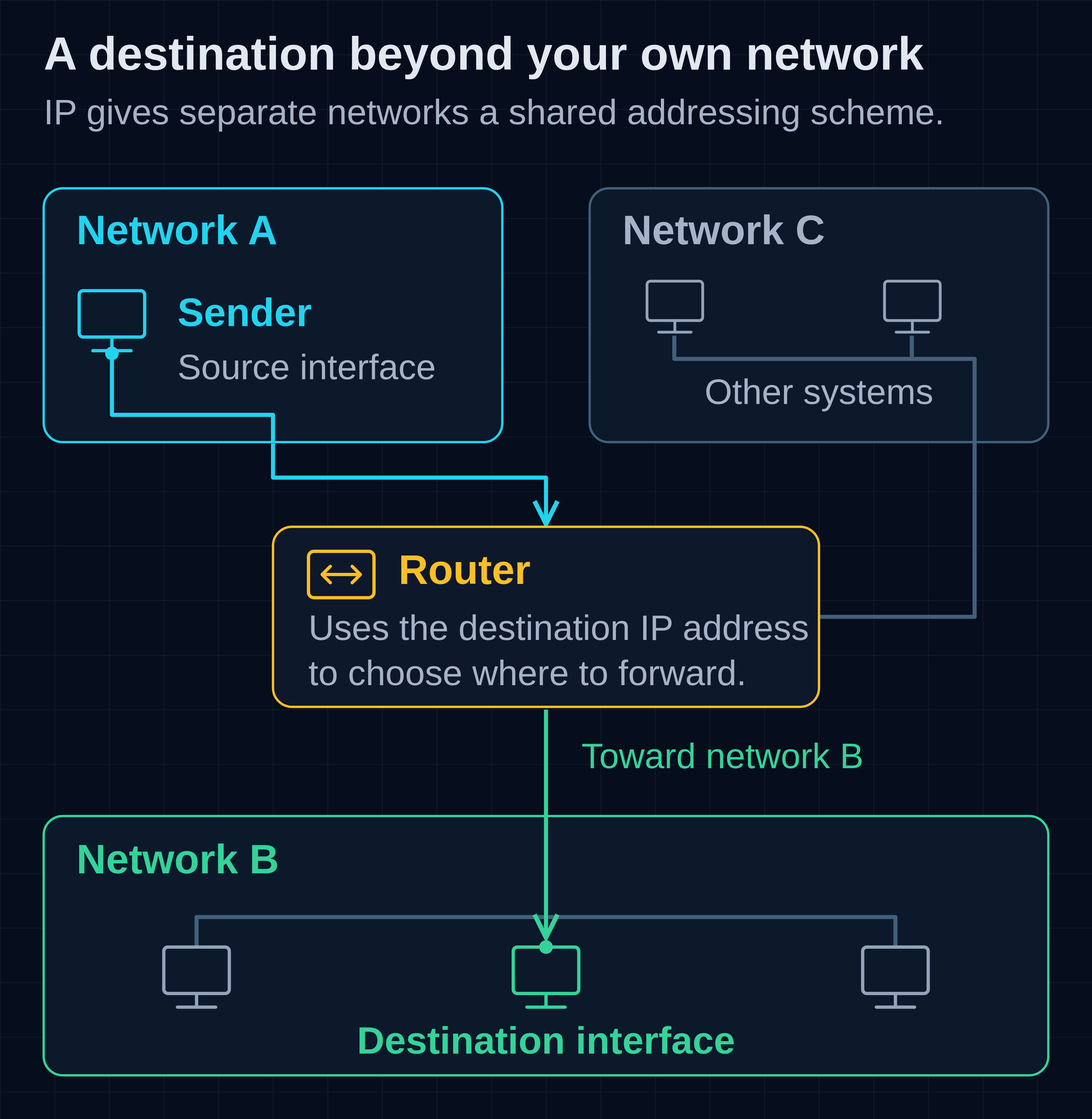
Conceptual example: the destination IP address guides forwarding toward network B, then delivery to the destination interface.
Before a network can deliver data, it needs a way to say where that data is going. Connecting several networks makes the problem harder: a destination must make sense beyond the sender's own network.
The early ARPANET had its own addressing arrangements; the four-site network in the 1969 map was not running IPv4. Its later NCP host protocol assumed communication through ARPANET and could not address networks beyond a destination Interface Message Processor, or IMP—the packet-switching computer connecting hosts to ARPANET. Internetworking required a scheme that could span independently operated networks. Cerf and Kahn's 1974 paper combined transport and forwarding in a protocol called TCP; the design subsequently separated into IP for addressing and forwarding, and TCP for reliable transport.[1]
The IPv4 specification published as RFC 791 in September 1981 describes addresses with a network part and a part identifying a destination within that network. That structure lets routers work with groups of destinations rather than an unrelated label for every computer. The boundaries and allocation practices have evolved, but this combination of an endpoint address and a routable network prefix remains central.[9][5]
What does an IP address identify?
An IP address is a numerical address used by the Internet Protocol. In an ordinary one-to-one exchange, it identifies a network interface: the point where a system connects to a network.
An IP packet carries a source address and a destination address, allowing the network layer to distinguish where it came from and where it should go.[2][9][24]
A laptop's Wi-Fi and Ethernet connections can have different addresses, and one interface can have more than one address. A router has interfaces on different networks. Addresses can also be reassigned as systems move or their configuration changes. An address therefore describes a network attachment in a particular context; it is not a permanent serial number for a device or proof of the identity of its user.[2][24][29]
How do you read an IPv4 address and its prefix?
An IPv4 address contains 32 bits, written as four decimal numbers separated by dots. Each number represents eight bits and ranges from 0 to 255. A suffix such as /24 tells you how many leading bits form the network prefix.
A bit is a binary digit, either 0 or 1; an octet is a group of eight bits. For example, 192.168.1.10 represents the bit pattern 11000000.10101000.00000001.00001010. The dots make the written address easier to read; the address itself is a single 32-bit value.[9]
The address alone does not tell a host which destinations are on its local network. For that, it also needs network configuration. Consider a home or small-office LAN—a local area network—with a laptop configured as 192.168.1.10/24 and a router whose LAN interface is 192.168.1.1. The /24 is a prefix length: the first 24 bits identify the subnet, leaving eight bits for addresses within it. Here the subnet is 192.168.1.0/24, covering 192.168.1.0 through 192.168.1.255. The equivalent subnet mask is 255.255.255.0; its set bits mark the prefix.[5]
That range contains 256 addresses, not 256 ordinary device assignments. In this conventional IPv4 /24, 192.168.1.0 identifies the subnet and 192.168.1.255 is its broadcast address, used to address all hosts on that subnet. This leaves 192.168.1.1 through 192.168.1.254 for interface addresses, including the router. The network/broadcast convention should not be generalized into a rule for every possible IPv4 prefix or for IPv6.[2]
Suppose the laptop has a connected route for this subnet and a default route through 192.168.1.1. A printer at 192.168.1.50 is on-link, so the laptop can send to it without asking the router to forward the packet. A destination outside that subnet requires another route; with only these two routes, traffic goes to the default gateway. A gateway is the next router, not the final destination. The destination address still identifies the remote server. Later we will follow the actual route lookup and the link-layer delivery to that next hop.[2]
The prefix is what makes the grouping explicit. Historically, IPv4's class A, B and C formats imposed fixed network/host boundaries, which fit growing networks poorly and contributed to inefficient allocation and large routing tables. Classless Inter-Domain Routing, or CIDR, replaced those classes with explicit, variable-length prefixes and allowed routes to be aggregated. It improved address use and routing scale; it did not enlarge the 32-bit address space. An address beginning with 192 does not by itself tell you that its present-day subnet is /24.[5]
How are public, private and LAN addresses different?
Public addresses come from globally coordinated address space intended for Internet routing. Private addresses can be reused within different organizations or homes. A LAN is a local network, not an address category: it can use private or public addresses.
The laptop's 192.168.1.10 belongs to private IPv4 address space. Private ranges can be reused without each network obtaining a globally unique allocation. This distinction concerns address scope, not whether the device is physically nearby.[25]
RFC 1918 reserves exactly these three IPv4 ranges for private use:
| Private prefix | Full address range |
|---|---|
10.0.0.0/8 |
10.0.0.0–10.255.255.255 |
172.16.0.0/12 |
172.16.0.0–172.31.255.255 |
192.168.0.0/16 |
192.168.0.0–192.168.255.255 |
Only the listed portion of 172 is private under RFC 1918. These ranges can be routed within an organization and between cooperating private networks, but they are not globally unique destinations to advertise across the public Internet. Two homes can both use 192.168.1.10; joining overlapping private networks through a VPN can therefore require renumbering or translation.[25]
A LAN is the local network itself, not an address category. It can use private IPv4, appropriately allocated public IPv4, or IPv6 addresses. Likewise, a public address does not guarantee that an application is reachable: there must be working routes in both directions, traffic must be permitted by policy, and a service must be listening. Address scope and access control answer different questions.[25][32]
How, then, does the privately addressed laptop reach a public service? A common IPv4 gateway uses Network Address Translation, or NAT. With the port-sharing form—Network Address Port Translation (NAPT), also called PAT—it translates outgoing source addresses and transport ports, allowing several private clients to share a public IPv4 address. It keeps mappings so replies can be translated back to the appropriate internal endpoint. Routing chooses the next hop; translation changes the addressing seen on the other side.[20]
This is a response to scarcity: 32 bits allow 4,294,967,296 distinct IPv4 values in total, and reserved uses mean fewer are available for public host addressing. Sharing public addresses stretches that resource, but translation alone is not a security guarantee. Stateful filtering and firewall policy can restrict incoming traffic, including on networks that use public addresses without NAT.[9][27][32]
The translation may also happen inside an Internet provider. Carrier-grade NAT can place multiple customers behind shared public addresses. Its designated shared range, 100.64.0.0/10, runs from 100.64.0.0 to 100.127.255.255; it is a separate special-purpose allocation, not a fourth RFC 1918 range. If a router receives an address from this range on its upstream interface, that address is not a globally reachable public IPv4 address.[33]
What changes with IPv6?
IPv6 expands addresses from 32 to 128 bits and uses a different packet format. It provides a much larger address space, with addressing scopes and configuration mechanisms described below. A system can support both versions, with separate addresses and routing information.
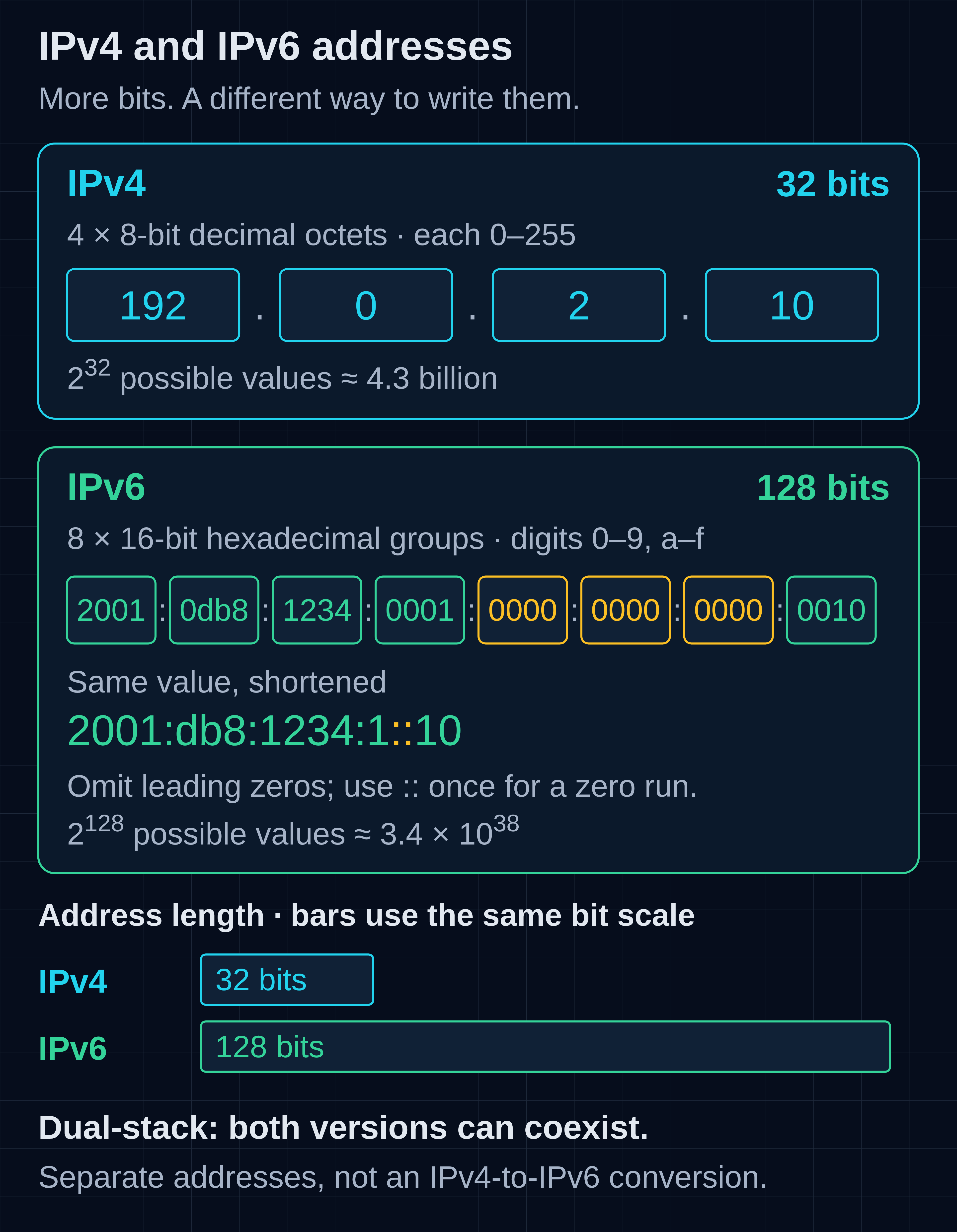
IPv4 and IPv6 address notation. Both examples use documentation-only addresses. The two IPv6 forms represent the same value: leading zeros are omitted, and the amber zero groups become ::. The bars compare address length, not address-space size; the counts show possible bit patterns, not usable public hosts. Dual-stack allows both versions to coexist with separate addresses.
Its first specification appeared as RFC 1883 in December 1995; the current base specification is RFC 8200. IPv6 is a distinct IP version, not just longer text for an IPv4 address.[23][8]
Writing 128 binary digits would be unwieldy, so IPv6 normally uses eight colon-separated groups of hexadecimal digits. Hexadecimal is base 16: the symbols 0–9 and a–f represent values zero through fifteen, and each digit represents four bits. Each full group contains four digits, or 16 bits. For example, 2001:0db8:1234:0001:0000:0000:0000:0010 can be shortened to 2001:db8:1234:1::10. Leading zeros within a group may be omitted, and one consecutive run of zero groups may be compressed to ::; using it twice would make the missing groups ambiguous. The final 10 here is hexadecimal, equal to sixteen in decimal.[24]
IPv6 also uses prefixes: in 2001:db8:1234:1::/64, the first 64 bits are fixed and the other 64 bits vary. The addresses beginning with 2001:db8 in this article are reserved for documentation, so they illustrate the notation without identifying a public service to contact.[24][28]
On an IPv6 LAN, an interface can have several useful addresses at once. A global unicast address is intended for communication beyond the local network and can be routed on the public Internet; it still needs routes and permission to be reachable. A unique-local address (ULA) is intended for local communications, potentially across several internal networks, rather than the public Internet. ULAs occupy fc00::/7; the locally assigned form uses fd00::/8, with a generated prefix to reduce the chance of clashes between sites. A link-local address, from fe80::/10, is narrower in scope: routers do not forward packets with link-local source or destination addresses to another link. Link-local addresses support functions such as discovering neighbours and routers.[24][26]
This makes the LAN/private distinction especially visible: the same laptop interface can have both a link-local address and a global address. IPv6 also has no broadcast addresses. Where communication needs to reach a group of interfaces, multicast serves that role rather than IPv4-style broadcasting.[24]
How does a system get its address, and where does DNS fit?
A system can have a statically configured address or obtain one automatically through DHCP or IPv6 autoconfiguration. DNS lets applications look up addresses associated with names. Address assignment configures an interface; name resolution helps an application find a destination.
DHCP—the Dynamic Host Configuration Protocol—commonly supplies an IPv4 address as a renewable lease, together with network configuration. It can also convey a deliberately fixed assignment. Both public and private addresses can be assigned automatically; “dynamic” does not mean “private.”[29]
IPv6 supports manual configuration and DHCPv6, as well as Stateless Address Autoconfiguration (SLAAC). With SLAAC, a host can form addresses using suitable prefixes advertised by a router rather than receiving each complete address from a DHCP server. Router Advertisements also support learning default routers; obtaining an address and learning how to leave the link are related but distinct functions. Whether an IPv6 destination is on-link follows advertised or configured information, not merely a visual resemblance between addresses.[30][7]
A few special addresses explain what we will see later. The IPv4 loopback range is 127.0.0.0/8, with 127.0.0.1 commonly used; IPv6 uses ::1. They let applications communicate within the same host, without sending their traffic through the LAN router. The unspecified addresses 0.0.0.0 and :: instead represent the absence of a specified address in relevant protocol contexts. They are not ordinary addresses for a remote service. Also distinguish 0.0.0.0 from the route prefix 0.0.0.0/0: the latter matches every IPv4 destination and is used for the default route.[27][24][5]
People usually choose a service by name rather than by its current numerical address. The Domain Name System (DNS) lets applications look up information associated with a name, including addresses. A name can have several addresses, and its records can change without the name changing. DNS supplies information used to choose a destination; it does not assign an interface its address, select the packet's route or establish the TCP connection.[31]
How does an addressed request become a connection?
Once the application has selected a server address, it can ask TCP to establish a connection to the server's port. IP routes the handshake packets toward that address; TCP establishes the connection state before ordinary application data is exchanged.
The next diagram uses the same subnet and gateway principles as the home-network example, but deliberately leaves out NAT so we can see routing and transport without translation changing the endpoints.
Imagine a client requesting a document from a server. We will use an illustrative client at 192.0.2.10, a router at 192.0.2.1 on the client's link, and a server at 198.51.100.20. These addresses come from the documentation-only ranges 192.0.2.0/24 and 198.51.100.0/24; they are neither RFC 1918 private ranges nor real public destinations to contact. The drawing models routing between these example networks, omitting NAT, proxies and additional routers to keep the original IP endpoints visible.[27]
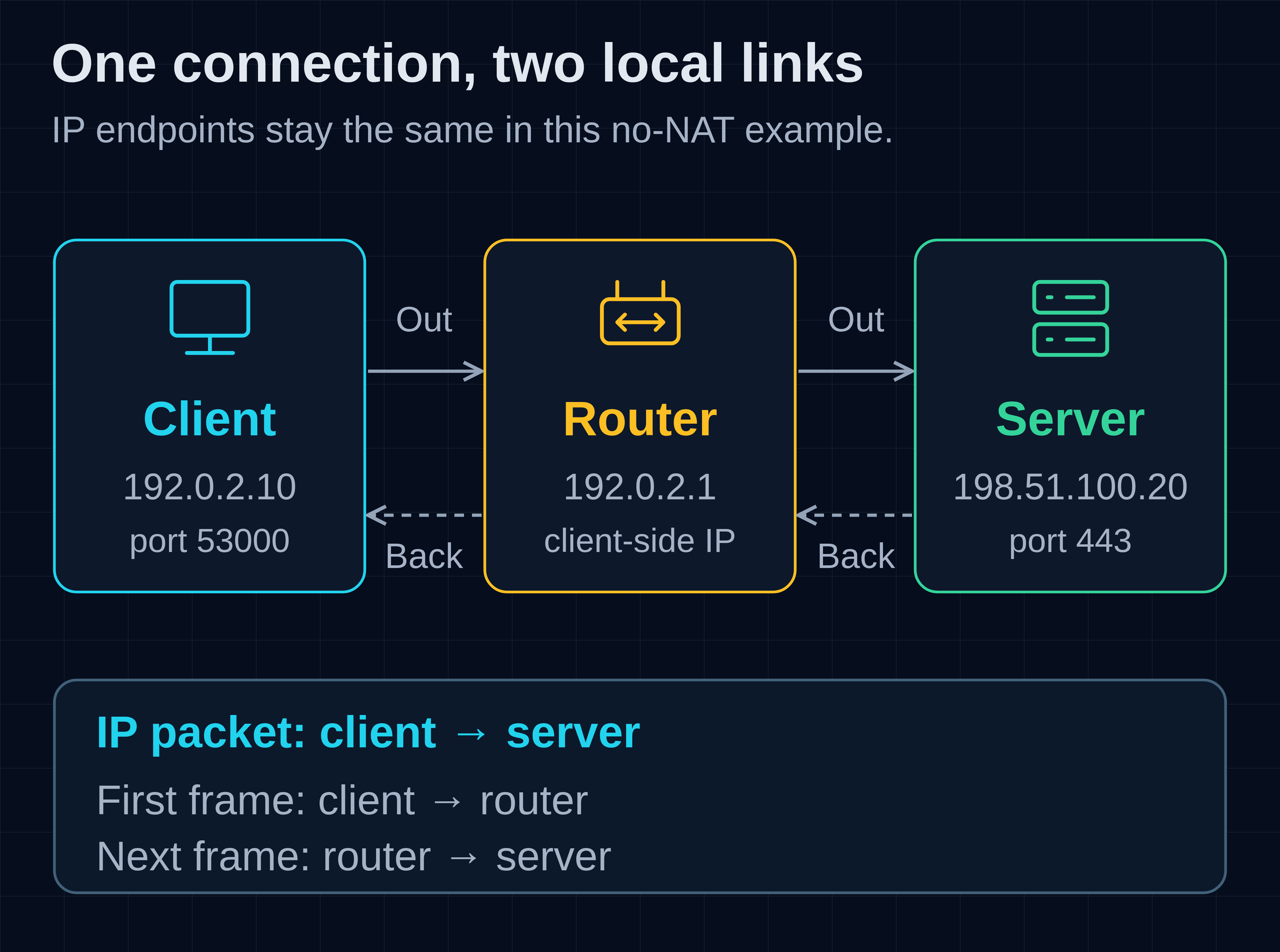
Figure 1. A request crosses two links through a router. The response travels back toward the client; a real return path need not use the same routers. This topology is illustrative, separate from the loopback experiment.
With the server address selected, the application can open a connection. For a conventional HTTPS connection using HTTP/1.1 or HTTP/2, TCP carries the TLS-protected application traffic. TLS provides the secure channel; HTTP describes the request and response. Not every web request uses TCP: HTTP/3 maps HTTP onto QUIC instead.[2][4]
For the main journey, suppose the client opens a TCP connection from local port 53000 to server port 443. Port 53000 is an illustrative ephemeral port chosen for this connection. The server has a listening socket associated with its service address and port. After accepting a connection, the server application communicates through a connected socket; the listening socket can continue accepting others.[3]
A connection is distinguished by its local and remote IP addresses and TCP ports. The response reverses those endpoints: its source port is 443, and its destination port is 53000. A port is not an independent network destination, and 443 does not uniquely identify one connection. Many clients can reach the same listener because their endpoint combinations differ. Operating systems additionally scope sockets within their networking contexts; the four endpoint fields identify a connection within that context.[3]
Why split the work into layers?
Layers separate responsibilities that change at different rates. An application can keep its protocol while a link changes from Ethernet to Wi-Fi; TCP can preserve its stream service while IP routes packets across different networks. The boundaries help explain behaviour without requiring every component to understand the whole conversation.[2][3]
The Internet architecture is commonly described with four layers: application, transport, Internet and link. A five-layer teaching model separates the physical medium from the link layer. The OSI model offers another useful vocabulary. TLS, tunnels and hardware offload illustrate where the boundaries between these models overlap or differ.[2]
For our request, IP offers best-effort packet delivery, not guaranteed arrival, order or freedom from duplicates. TCP supplies the stronger stream service above it; it does not make individual IP packets infallible.[2][3]
The important distinction is between the data an application handles and the units carried between networking components:
- Application bytes: the contents of the conversation, with meaning defined by HTTP or another application protocol.
- TCP segment: a TCP header plus a portion of the stream, or control information such as a SYN or ACK.
- IP packet: an IP header and its payload, which here contains a TCP segment, before any IP fragmentation.
- Link frame: the unit carried across a particular link, such as an Ethernet frame carrying that IP packet.[2][3]
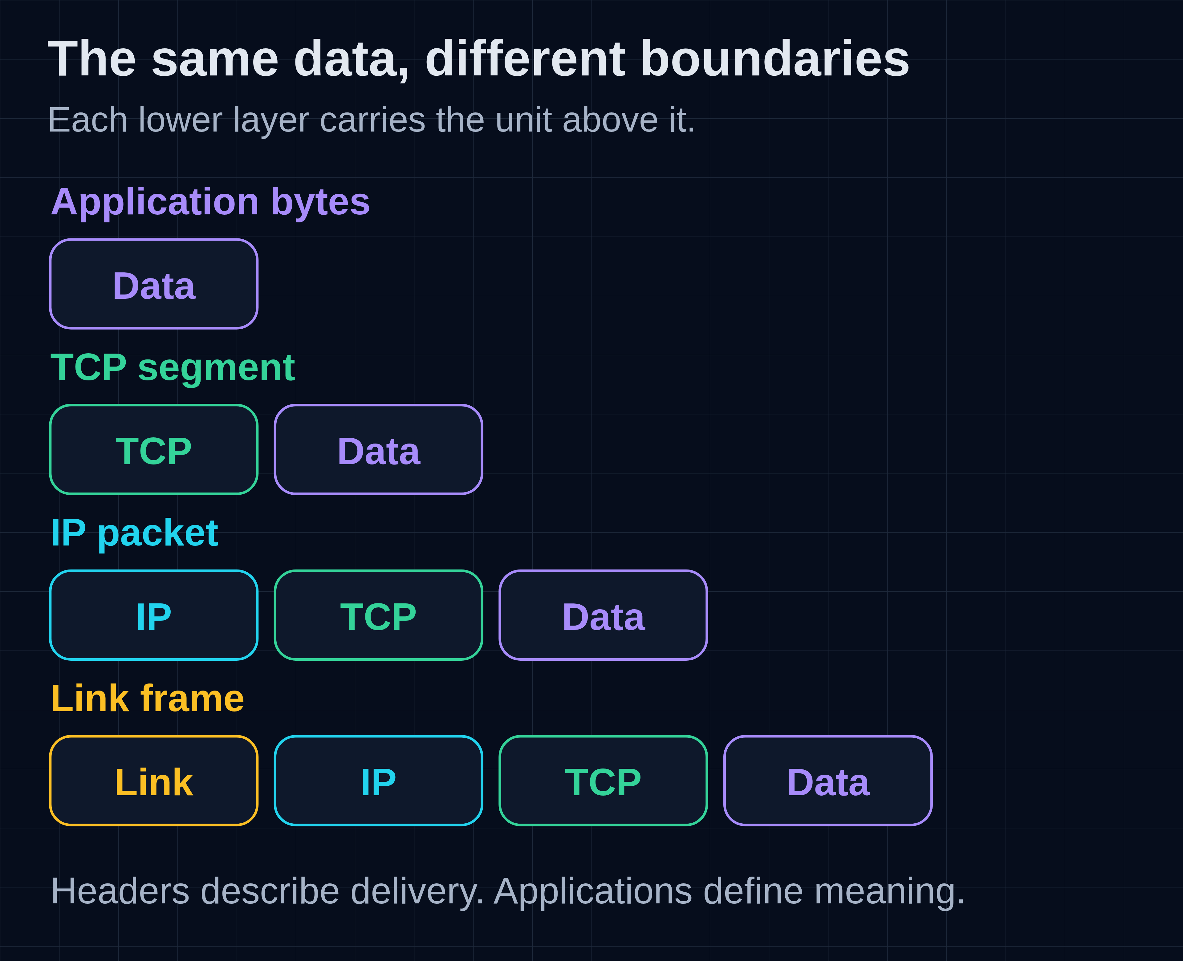
Figure 2. Encapsulation adds headers around data. This simplified view shows one TCP segment in one unfragmented IP packet; it does not imply one application write becomes one segment. Ethernet also has a trailer, omitted here.
What is actually inside an IP packet and a TCP segment?
An IP packet contains an IP header and a payload. For TCP traffic, that payload contains a TCP segment: its header and any application data. IP fields describe addressing and forwarding; TCP fields describe ports, byte positions and connection control.
Reading their layouts makes it easier to understand where the payload begins, what changes at a router and what an acknowledgement describes.
How do you read a header diagram?
Read left to right, then continue on the next row. Each full row represents 32 bits, or four bytes. Field widths show their bit counts, and byte offsets locate them within the header. Multi-byte numeric fields use network byte order, with the most significant byte first.
The bit positions restart at zero on each row; the byte offsets at the left count from the beginning of that particular header. These are drawings of a continuous sequence of bytes, not separate records transmitted row by row. For example, the two-byte value 0x1234 appears as 12 followed by 34. The leftmost bit of each byte is its most significant bit.[9][3]
Field widths in the fixed-header grids are proportional to their bit counts. A 16-bit field occupies half a row; a 128-bit IPv6 address occupies four full rows. Variable-length options and payload are shown as separate bands, not to scale. The right edge marked 32 is the boundary after bit 31, not an additional bit.
A header holds protocol information; a payload is what that protocol carries. Those terms are relative to a layer. In our unfragmented TCP-over-IPv4 example, the IP payload is the complete TCP segment—TCP header plus any TCP data. The TCP payload is only the bytes after its own header. A segment can also carry control information without application data, as with a pure ACK. This is why the informal expression “TCP packet” usually refers to an IP packet containing a TCP segment.[3]
What does each IPv4 header field do?
IPv4 header fields identify the source and destination, describe packet and header lengths, limit forwarding, identify the carried protocol, control fragmentation and check header integrity. The header occupies 20–60 bytes; its length tells the receiver where the payload begins.
The IPv4 header starts with a fixed 20-byte portion and can grow to 60 bytes when options and padding are present. Its total-length field describes the entire IP packet. These measurements determine how much application data fits under an MTU.[9]
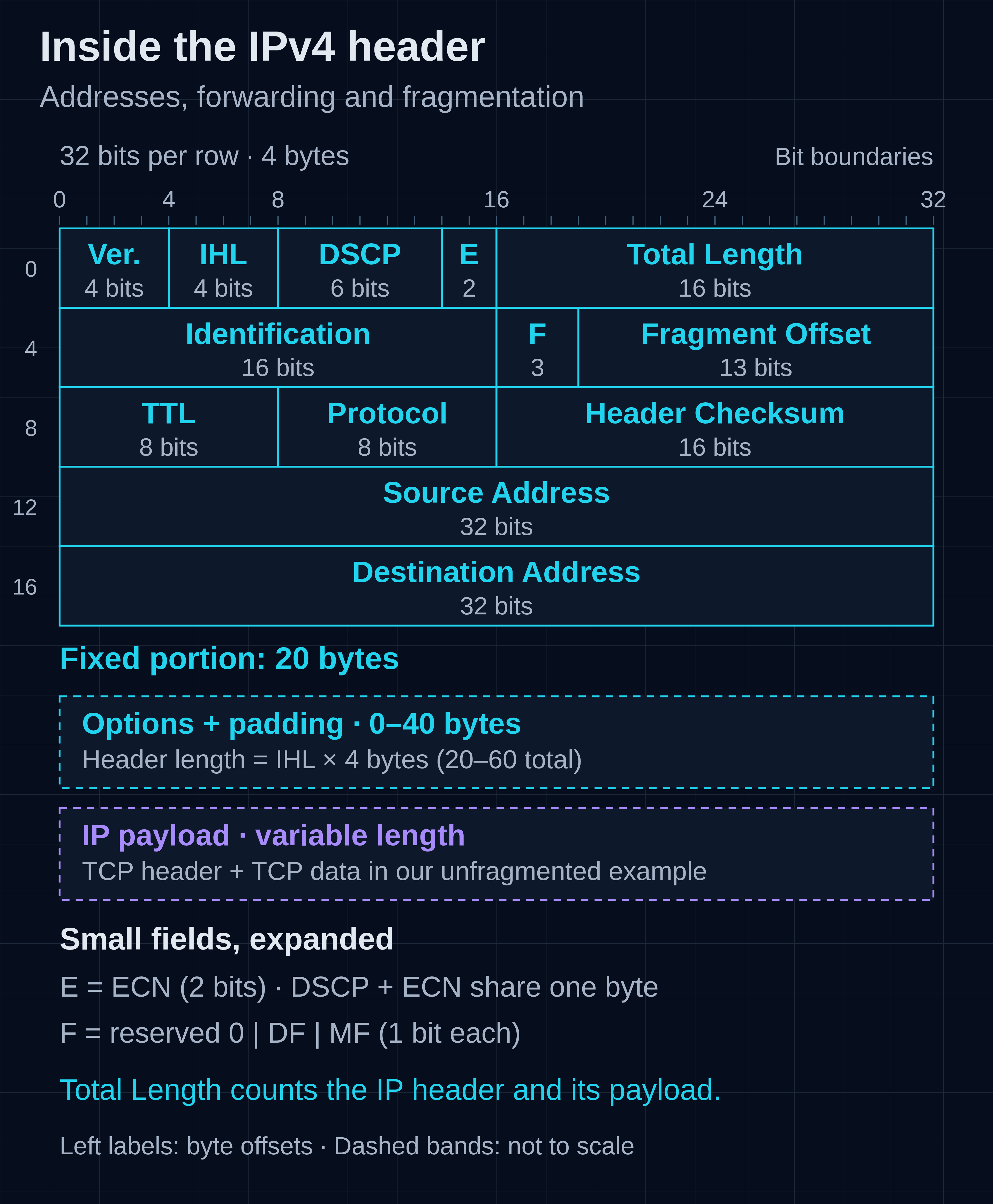
IPv4 header anatomy. Fixed fields are drawn to their bit widths. E marks the two ECN bits; F marks the three fragmentation flags. Options, padding and payload have variable lengths and are not drawn to scale.
Version and Internet Header Length (IHL), four bits each. Version is 4. IHL counts 32-bit words in the IPv4 header, including options and padding: 5 means 20 bytes, while the largest four-bit value, 15, means 60 bytes. For an ordinary unfragmented TCP packet, the TCP header begins immediately after those IP-header bytes. IHL describes the IP header, not the TCP header or the entire packet.[9]
DSCP, six bits, and ECN, two bits. Older drawings label this whole byte “Type of Service” or “TOS.” Its modern interpretation separates the Differentiated Services Code Point, used to select configured per-hop traffic treatment, from Explicit Congestion Notification. DSCP can influence queueing or forwarding treatment under a network's policy; setting it does not reserve end-to-end bandwidth. ECN distinguishes non-ECN-capable traffic (00), the two ECN-capable codepoints (01 and 10), and Congestion Experienced (11). A participating congested router can mark suitable ECN-capable traffic rather than signal congestion solely through loss. TCP's feedback for that mark appears in its own header, described below.[34][35]
Total Length, 16 bits. This is the number of bytes in the IPv4 header plus its payload. A value of 1500 with IHL 5 leaves 1,480 bytes after the IP header; that space must accommodate both the TCP header and TCP data. The field's maximum value is 65,535 bytes, although the path's usable packet size is usually much smaller. Each IPv4 fragment has its own header and Total Length.[9]
Identification, 16 bits; Flags, three bits; Fragment Offset, 13 bits. These fields describe IP fragmentation, not TCP's ordering of application bytes. Identification helps associate fragments of one original datagram, together with its source, destination and protocol. It is not a TCP sequence number or a universal counter of all packets. Modern rules do not require a unique Identification value for an atomic IPv4 datagram—one with DF set, MF clear and offset zero.[9][36]
The three flag bits, in order, are reserved (zero), DF (Don't Fragment) and MF (More Fragments). DF tells a router not to fragment the packet. MF means more fragments follow; the final fragment has MF clear. The offset gives this fragment's position in the original IP payload in eight-byte units. Thus offset 185 places its data at byte 1480 of that payload. A nonzero offset can identify a later fragment even when MF is clear. The destination reassembles the IP payload before TCP processes the complete segment; later fragments do not each acquire a new TCP header.[9]
Time to Live (TTL), eight bits, and Protocol, eight bits. TTL limits how long a packet can keep being forwarded; routers decrement it, preventing a routing loop from circulating the same packet forever. Protocol identifies the protocol carried in the reassembled IP payload: 6 means TCP, while 17 means UDP. It does not identify the application port. Our request therefore has IP Protocol 6 and TCP destination port 443, in different headers.[9][3][18]
Header Checksum, 16 bits. IPv4 checks its header, including any options, but not the IP payload. A router changing TTL must also update this checksum. The one's-complement checksum detects many accidental corruptions; it is not cryptographic authentication and cannot establish that an address or packet is trustworthy. TCP applies its own checksum to a different scope.[9][3]
Source and Destination Address, 32 bits each. These are the binary addresses introduced earlier: in our outgoing example, 192.0.2.10 and 198.51.100.20. The ordinary header does not contain the client's subnet mask or its default gateway. Those belong to the host's configuration and routing information. The router uses the destination to make its own next-hop decision.[9][2]
Options and padding, zero to 40 bytes together. IPv4 options can carry additional network-layer information, such as record-route or timestamp information. Padding brings the header to a whole number of four-byte words. Both are included in IHL and the IPv4 header checksum. The payload begins only after them, so assuming every IPv4 header is exactly 20 bytes can put a decoder at the wrong location.[9]
How is the IPv6 base header different?
IPv6 uses a fixed 40-byte base header. Longer addresses occupy most of it, while optional network-layer information goes into separate extension headers after the base. It has no IHL field, no base-header fragmentation fields and no IPv4-style header checksum.[8]
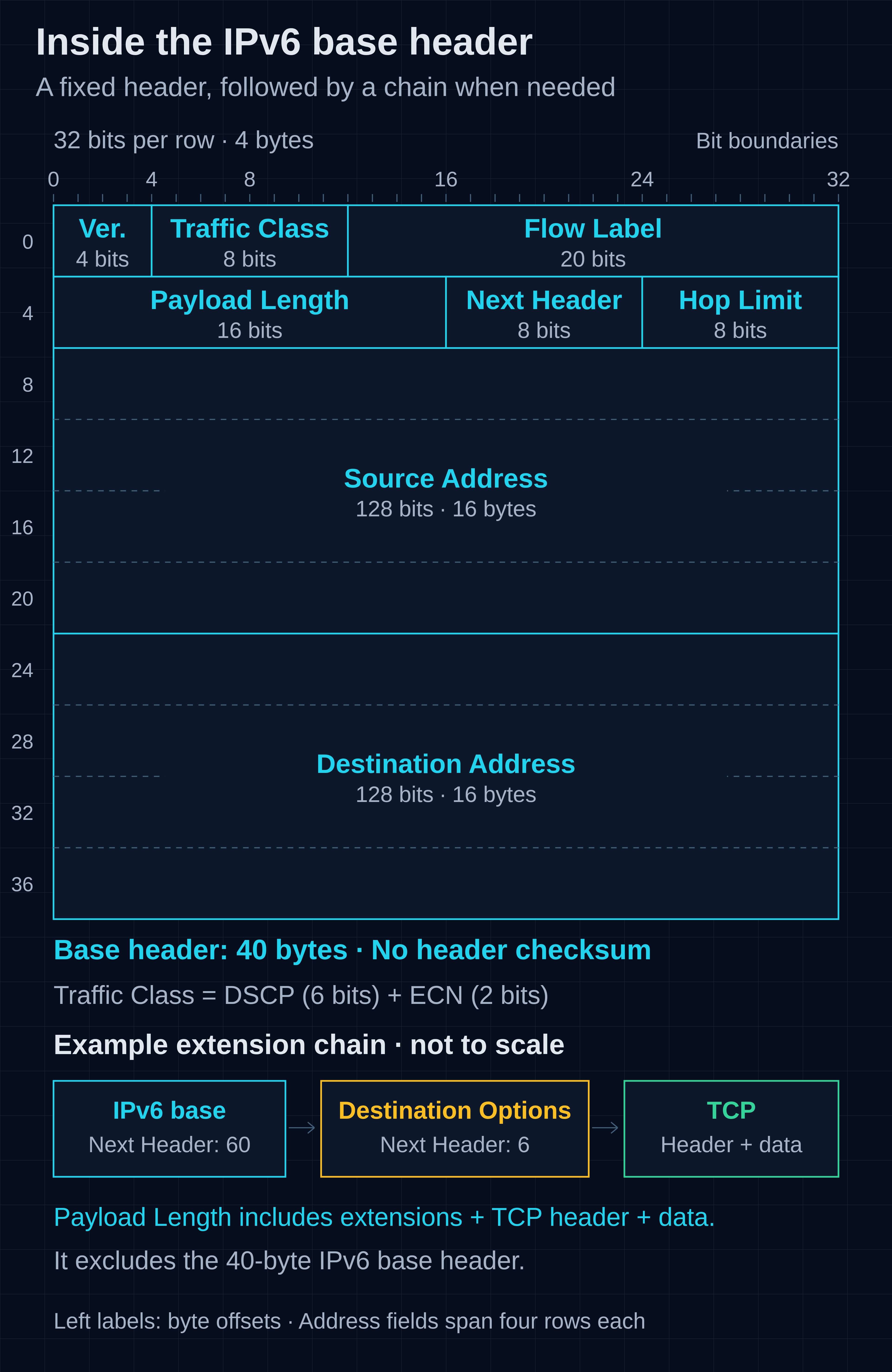
IPv6 header anatomy. The ten four-byte rows total 40 bytes. The example below the grid shows how Next Header links a base header, an optional Destination Options header and TCP; that chain is schematic, not to scale.
Version, four bits; Traffic Class, eight bits; Flow Label, 20 bits. Version is 6. Traffic Class provides the same six-bit DSCP and two-bit ECN split discussed for IPv4. The Flow Label lets a source label a flow of packets for flow-specific handling; it is neither a TCP port nor a byte sequence number. It does not itself reserve bandwidth or make IP delivery reliable.[8][34][35]
Payload Length, 16 bits. Unlike IPv4's Total Length, this counts everything after the fixed base header. That includes any extension headers as well as the transport header and transport data. An ordinary 1,500-byte IPv6 packet therefore has Payload Length 1460; adding the 40-byte base header recovers its total size. The specialized IPv6 jumbogram mechanism is outside this example.[8]
Next Header, eight bits. This identifies the header immediately following the current one. If the base header says 6, TCP follows directly. If it identifies an extension header, that header's Next Header value continues the chain. For example, base Next Header 60 can identify Destination Options, whose Next Header 6 then identifies TCP. Consequently, “the TCP header starts 40 bytes into IPv6” is true only when no intervening extension headers are present.[8]
Hop Limit, eight bits. Each forwarding node decrements this limit by one and discards the packet if forwarding exhausts it. It serves the loop-limiting role discussed for IPv4 TTL. Because IPv6 has no base-header checksum, changing Hop Limit does not require an IPv4-style header-checksum update.[8]
Source and Destination Address, 128 bits each. Each occupies sixteen bytes—four rows in the drawing. They carry the full binary addresses, irrespective of how many characters their compressed textual forms use. In the ordinary case they identify the originating and receiving interfaces; a Routing extension header can affect which destination is currently named in the base header.[8]
Extension headers and the upper-layer payload. Extensions are outside the fixed base header but inside its payload-length count. A Fragment header, when needed, carries IPv6's fragmentation information. Only the source fragments IPv6 packets; a forwarding router that cannot carry the packet sends Packet Too Big feedback instead. The larger base header, any extensions and the actual TCP header all consume space under the MTU.[8]
What does the TCP header add?
The TCP header adds source and destination ports, sequence and acknowledgement numbers, control flags, a receive window and integrity checking. It occupies 20–60 bytes, including any options and padding, and describes one segment in a bidirectional byte-stream conversation.
The same basic TCP layout works over IPv4 and IPv6; IP addresses remain in the IP layer rather than being repeated as transmitted fields inside TCP.[3]
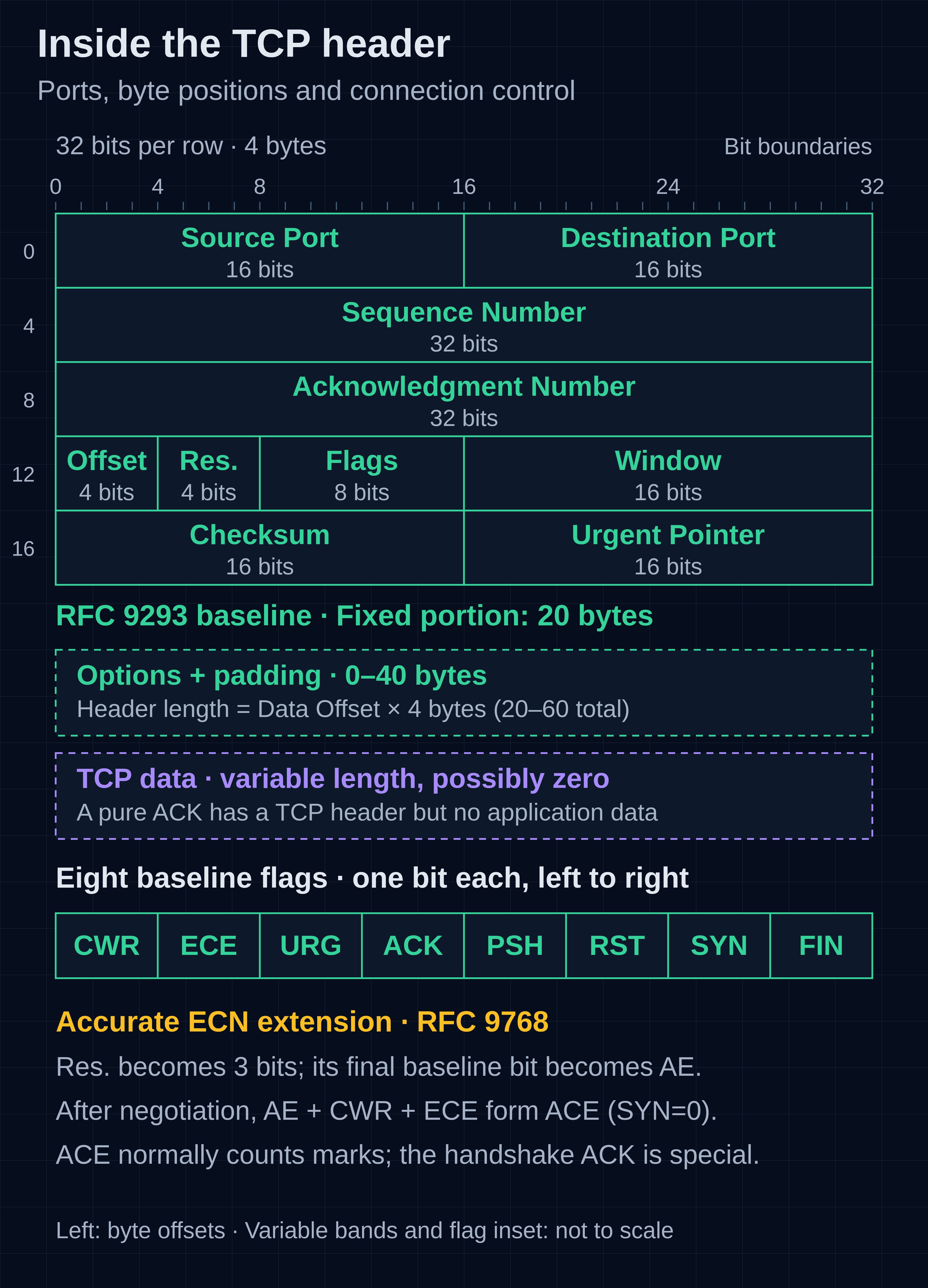
TCP header anatomy. The main grid shows the RFC 9293 baseline: four reserved bits and eight named flags. The inset expands those flags for readability. The note distinguishes the newer Accurate ECN allocation; it does not add bytes to the header.
Source and Destination Port, 16 bits each. For our client-to-server segment these are 53000 and 443. Together with the IP addresses, they identify the communicating endpoints. Reply segments reverse the ports. A port number says where TCP delivers the bytes, not what those bytes mean or whether TLS has authenticated the peer.[3]
Sequence Number and Acknowledgment Number, 32 bits each. The sequence number identifies the first data byte carried by this segment, except that a SYN uses the initial sequence number and the first data byte follows it. The acknowledgement field, when ACK is set, identifies the next sequence number expected from the other direction. Each direction has its own numbering. SYN and FIN each consume one sequence position; a pure ACK consumes none. The handshake example below will apply these fields to concrete byte positions, including the ten-byte request.[3]
Data Offset, four bits. This counts four-byte words in the TCP header. A value of 5 means data begins after 20 bytes; 8 means after 32 bytes; 15 allows 60 bytes. Unlike IPv4's Total Length, it does not describe the whole segment. TCP has no separate total-segment-length field: the enclosing IP information determines the segment's extent after reassembly and any intervening headers are accounted for.[3][8]
Reserved bits and flags. The baseline layout in RFC 9293 assigns four reserved bits followed by eight one-bit flags. Reserved bits are sent as zero when their corresponding future features are not implemented. The flags can be combined: SYN-ACK means both SYN and ACK are set in the same segment. Read the baseline flag region from left to right:[3]
| Flag | Meaning in the baseline or Classic ECN interpretation |
|---|---|
| CWR | Congestion Window Reduced: part of TCP's Classic ECN feedback exchange, including acknowledging a response to congestion feedback. |
| ECE | ECN-Echo: supports Classic ECN negotiation and, during data transfer, reports congestion marking back to the sender. |
| URG | The Urgent Pointer field is significant. |
| ACK | The Acknowledgment Number field is significant. |
| PSH | Requests the push function, making received data available promptly rather than waiting for more data; it does not define an application-message boundary. |
| RST | Resets or aborts the connection. |
| SYN | Synchronizes initial sequence numbers when establishing a connection. |
| FIN | Indicates no more data will be sent in this direction. |
Classic ECN uses ECE and CWR during the handshake to establish support, then to return congestion feedback and acknowledge the sender's response. That connects IP's two ECN bits to TCP's congestion-control behaviour; an IP congestion mark and a TCP ECE flag are different fields travelling in the data and feedback directions.[35]
There is a newer interpretation worth recognizing in packet analyzers. The current IANA registry assigns the last of the baseline reserved bits to AE (Accurate ECN) under RFC 9768, leaving three reserved bits. Some older drawings call that position NS, from the now-historic ECN Nonce experiment. Accurate ECN is negotiated during the handshake: the client requests it by setting AE, CWR and ECE in its SYN, and the server's SYN-ACK indicates whether it is supported. After successful negotiation, on segments with SYN clear, those three positions form the ACE field for more detailed ECN feedback. It normally carries the low three bits of a counter of CE-marked packets; a pure final handshake ACK without SACK blocks has a special encoding. Without the negotiated mode, those positions must not simply be decoded as an ACE counter. The bit positions change meaning, not the header's byte length.[37][38]
Window, 16 bits. This advertises how much data the sender of this segment is currently willing to receive, starting at the byte identified by its acknowledgement. In a server-to-client ACK, it therefore constrains how much the client may send. Window scaling, negotiated in the SYN exchange, lets this field represent larger receive windows. The congestion window, cwnd, is separate sender-side state and is not another transmitted TCP-header field. We will use that distinction in the flow-control example later.[3][39]
Checksum, 16 bits. TCP checks its complete header, including options, and its data, plus a pseudo-header built from IP-layer information. That pseudo-header is input to the checksum calculation, not an extra header transmitted before TCP. For IPv4 it contains the 32-bit source and destination addresses, eight zero bits, the eight-bit protocol value 6, and a 16-bit TCP length covering TCP header plus data. For IPv6 it contains the 128-bit source and destination addresses, a 32-bit upper-layer length, 24 zero bits and the eight-bit upper-layer Next Header value 6. IPv6 extension headers are excluded from that TCP length; if a Routing header is present, the pseudo-header uses the final destination address.[3][8]
The TCP checksum is required over both IP versions. It helps detect accidental corruption and misdelivery, but provides no cryptographic authentication or resistance to deliberate modification. TLS supplies a different kind of protection above TCP. Ordinary router changes to TTL or Hop Limit do not alter the TCP checksum's inputs, whereas translation of an address or TCP port does affect them.[3][20]
Urgent Pointer, 16 bits. When URG is set, this is an offset from the segment's sequence number to the sequence position immediately after the urgent data. It does not create a separate high-priority packet queue or replace application framing. It matters only under the urgent-data mechanism; ordinary request/response data need not use it.[3]
How do TCP options affect the handshake and payload?
TCP options can advertise or negotiate capabilities such as maximum segment size, window scaling, selective acknowledgements and timestamps. They extend the header before its payload, consuming space under the packet-size limit. Data Offset identifies where TCP data begins.
Options occupy the space between the fixed 20 bytes and the start indicated by Data Offset. Most options encode a kind, a length and option data; the one-byte No-Operation and End of Option List forms are exceptions. Padding completes a four-byte boundary, and these bytes count as header, not application data.[3]
Four commonly encountered options explain why a real SYN has more detail than a minimal handshake drawing:
- Maximum Segment Size (MSS) advertises the largest TCP data segment the endpoint can receive, with the fixed IP and TCP headers excluded. It is sent on SYN-bearing segments. Each endpoint advertises its own receive limit, which constrains the other endpoint's sending; it is not a single shared size chosen by the client.
- Window Scale announces a shift count for interpreting that endpoint's later receive-window advertisements. Both sides must offer the option in their SYN-bearing segments to enable scaling. Each direction can use a different count, and the Window field in SYN and SYN-ACK is never scaled.
- SACK Permitted advertises support during the SYN exchange. Later SACK options can report received byte ranges beyond a gap, supplementing the ordinary cumulative acknowledgement.
- Timestamps carry a timestamp value and an echoed value. Negotiation starts in SYN/SYN-ACK; subsequent timestamp exchanges support RTT measurement and protection against old duplicates when sequence numbers wrap. These are protocol clock values, not necessarily wall-clock times.[3][14][39]
For example, if the server advertises MSS 1460 in its SYN-ACK, that informs the client's sending direction. If both sides also negotiate window scaling and the server announces a shift of 7, a later server Window field of 512 represents 65,536 bytes of receive space. That is the receive-window value used later in Figure 4; the server's initial SYN-ACK window remains unscaled. These are illustrative negotiated values, not observations from the loopback test.[39]
Options also consume real packet space. With a 1,500-byte IPv4 MTU, a 20-byte IP header and a 32-byte TCP header, only 1,448 bytes remain for TCP data. The no-options example later has 1,460 bytes because its TCP header is twelve bytes shorter. This is why a decoder must follow IHL, extension headers and Data Offset rather than assume every packet has the same header lengths.[3]
We can now connect the header fields to the journey: IP supplies the addresses and forwarding limits, TCP identifies the application endpoints and byte positions, and each layer's length rules locate what it carries.
At the router, the incoming link frame is not forwarded intact across every subsequent network. The router processes the IP packet and sends it using the next link's framing. In our no-NAT example, the source and destination IP addresses still identify the client and server, while the link-layer addresses identify the participants on each individual link.[2]
This distinction answers an otherwise puzzling question: a client can send a frame to its local router while the IP packet inside is addressed to a server elsewhere. To do that, it first has to decide which destination is local and which requires a next hop.
How does a host choose the next hop?
A host consults its routing information to choose an outgoing interface and, when needed, a next-hop router. IP prefixes describe address ranges. Within the selected routing table, a more-specific matching route wins over a less-specific one; the default route is the least-specific fallback.[5]
In our routed example, 192.0.2.0/24 has the same prefix structure as the home LAN introduced earlier: the first 24 bits identify the subnet. We can now make the next-hop decision explicit with a routing table.
Suppose our client has 192.0.2.10/24 on an Ethernet interface, an on-link route for 192.0.2.0/24, and a default route through 192.0.2.1:
192.0.2.0/24       directly connected
0.0.0.0/0         via 192.0.2.1
A destination such as 192.0.2.20 matches the on-link route. The server at 198.51.100.20 does not, so this table sends its traffic to the default router. The default gateway is a next hop, not a replacement destination address in the original IP packet.
Now add a route for 198.51.100.0/24 through another reachable next hop. That route is more specific than /0, so it takes precedence for the server. Add a /32 route for that one server and it is more specific again. This is longest-prefix matching. Policy routing can select different tables, and equal-prefix alternatives need further selection rules.[5]
The client now knows the next hop's IP address, but an Ethernet interface needs a link-layer destination. For IPv4 over Ethernet, Address Resolution Protocol (ARP) resolves that local IP address to an Ethernet address. For our remote server, the client resolves the router's local address—not the server's distant Ethernet address. ARP requests remain on the local link.[6]
IPv6 resolves the local next hop through Neighbor Discovery rather than ARP. Carried in ICMPv6, Neighbor Discovery provides address resolution, router discovery and neighbour-reachability functions, using the on-link and router information introduced earlier.[7][8]
Each forwarding router repeats a next-hop decision using its own information. A path is therefore a series of local forwarding decisions, not a complete route encoded in every ordinary packet. The IPv4 Time to Live (TTL) and IPv6 Hop Limit prevent packets from circulating indefinitely: forwarding consumes the limit, and an exhausted packet is discarded. Despite the IPv4 field's historical name, it is not an application timeout or a measurement of remaining seconds.[8][9]
What happens when a packet is too large?
A link's maximum transmission unit, or MTU, limits the IP packet size it can carry without IP fragmentation. TCP must account for the smallest MTU along the path—the path MTU—when forming segments. A large application write is not a demand for one large packet.[3][9]
A familiar worked example assumes a 1,500-byte IP MTU, a 20-byte IPv4 header and a 20-byte TCP header, with no options. That leaves 1,460 bytes for TCP data. With IPv6's 40-byte base header and the same TCP header, it leaves 1,440 bytes. Options, extension headers and encapsulation can change the space available in these examples.[3][8]
The MSS exchange described above sets a receive constraint for each direction. The sender also has to respect the path and subtract any actual option or extension-header overhead from the payload it sends. An MSS exchange does not by itself discover every bottleneck MTU between the endpoints.[3]
There are two different kinds of splitting here:
- TCP segmentation divides the byte stream into independently sequenced transport segments. TCP at the receiver reconstructs the ordered stream.
- IP fragmentation divides one IP datagram into fragments. IP must reassemble that datagram at the destination before passing its complete payload upward.[3][8][9]
IPv4 routers can fragment eligible packets when the Don't Fragment (DF) flag is clear. With DF set, an oversized packet is discarded and the router can return an ICMP “fragmentation needed” message. Classical IPv4 Path MTU Discovery uses that feedback to reduce the sender's packet size.[9][10]
IPv6 routers do not fragment packets in transit. They return ICMPv6 Packet Too Big feedback; if fragmentation is used, it is performed by the source. IPv6 Path MTU Discovery uses that feedback to adapt to the path.[8][11]
This explains a specific failure pattern: a small handshake succeeds, but a larger transfer stalls. If required ICMP feedback is filtered or lost, the sender may not learn that its packets are too large. Packetization Layer Path MTU Discovery can instead use transport-level probes and delivery feedback to discover usable sizes. Recovery depends on the implementation supporting and using that mechanism.[11][12]
A successful connection establishes that some packets made the round trip; larger packets, sustained traffic and application operations may encounter different constraints.
How does TCP establish a conversation?
TCP's usual three-way handshake synchronizes the two directions' sequence spaces and establishes connection state. The client sends SYN, the server replies with SYN-ACK, and the client acknowledges it. That creates a transport connection; it does not authenticate the server or confirm that a request has been processed.[3]
Each direction has its own sequence numbers. They count bytes in the stream, not application messages or packet numbers. SYN and FIN each consume one position in sequence space, even though they are not application-data bytes. An ordinary acknowledgement without data does not.[3]
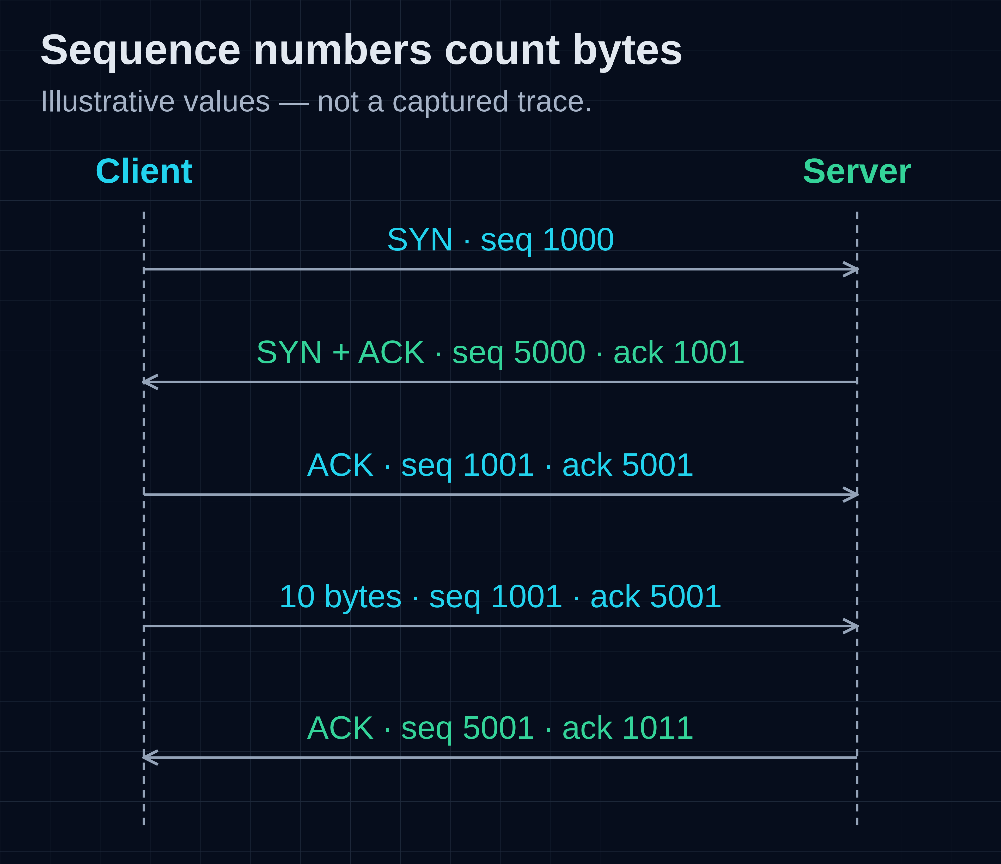
Figure 3. Illustrative sequence numbers, not a packet capture. The client starts at 1000 and the server at 5000. After the SYN, ten client data bytes occupy positions 1001 through 1010; ACK 1011 identifies the next expected byte. Options and possible ACK combinations are omitted.
The server's ACK 1001 acknowledges the client's SYN. The client's ACK 5001 acknowledges the server's SYN. If the client then sends ten bytes starting at sequence number 1001, the server can acknowledge through them with ACK 1011. The acknowledgement identifies the next expected byte in the stream.[3]
That acknowledgement means the receiving TCP has accepted the bytes, not that the server application has read them, validated the request or committed a database transaction. A transport connection can remain established while its application is stuck. TCP itself also provides neither encryption nor cryptographic peer authentication; those are additional responsibilities.[3]
Even before considering losses, this byte-stream model has a direct consequence for ordinary application code: the receiver must decide where messages begin and end.
Why can one write require several reads?
TCP preserves byte order, not the boundaries of application writes. One write may be split across reads; bytes from several writes may be returned together. A receiver must use the application's framing rules rather than assume that one recv() returns one complete message.[3]
HTTP has its own framing rules. A smaller custom protocol might use a fixed length, a delimiter or a length prefix. These choices belong to the application protocol, not to TCP. A length-prefixed protocol must still read the entire prefix and body, bound the permitted length and decide how to handle an incomplete message.
Here is a deliberately small fixed-length exchange that you can run with Python 3. It binds only to 127.0.0.1, asks the operating system for an available port and exits after one connection. It needs no external service, elevated privileges or extra packages. Save it as stream.py:
import socket
from concurrent.futures import ThreadPoolExecutor


def read_exact(sock, count):
    data = bytearray()
    while len(data) < count:
        chunk = sock.recv(count - len(data))
        if not chunk:
            raise EOFError("connection ended before the frame was complete")
        data.extend(chunk)
    return bytes(data)


def server(listener):
    conn, _ = listener.accept()
    with conn:
        conn.settimeout(5)
        first = conn.recv(3)
        print("First read:", first)
        rest = read_exact(conn, 10 - len(first))
        print("Complete request:", first + rest)
        assert first + rest == b"HELLOWORLD"
        assert conn.recv(1) == b""  # Client has finished sending.
        conn.sendall(b"OK")         # The other direction still works.


with socket.socket(socket.AF_INET, socket.SOCK_STREAM) as listener:
    listener.settimeout(5)
    listener.bind(("127.0.0.1", 0))  # Ask the OS for an unused local port.
    listener.listen(1)
    with ThreadPoolExecutor(max_workers=1) as pool:
        task = pool.submit(server, listener)
        with socket.create_connection(listener.getsockname(), timeout=5) as client:
            client.sendall(b"HELLOWORLD")
            client.shutdown(socket.SHUT_WR)
            print("Reply:", read_exact(client, 2))
        task.result()
Run it:
python3 stream.py
This local execution returned:
First read: b'HEL'
Complete request: b'HELLOWORLD'
Reply: b'OK'
The client made one sendall() call with ten bytes, but the server's first read asked for at most three. It could not return the entire request. On another run, that first read could return fewer than three bytes; the loop still reconstructs the exact ten-byte message. This demonstrates application read boundaries; determining the transmitted segment count would require packet-level observation.[3][13]
sendall() handles partial sends for the caller, continuing until it has sent the supplied bytes or encounters an error. It does not wait for an application-level acknowledgement. The read_exact() loop handles partial reads and rejects EOF before the frame is complete. The five-second socket timeout bounds an individual blocking operation here; a larger application may also need an overall request deadline.[13]
The final two lines of the exchange reveal something else. The client calls shutdown(SHUT_WR), ending its sending direction, but then receives OK. TCP is bidirectional: finishing one direction does not inherently prevent data flowing in the other.[3][13]
The transport still has more work than this quiet loopback exchange reveals. Across a real path, a segment can arrive late, twice, out of order or not at all.
How does TCP recover missing data?
TCP tracks bytes sent and acknowledged, detects missing data and retransmits when needed. The receiver can buffer out-of-order data, but the ordinary stream interface delivers bytes in order. Data beyond a gap does not become a separate complete message merely because it has already reached the host.[3]
Suppose the receiver expects byte 2001. It receives bytes 3001–4000 first because the earlier range is delayed or lost. Its cumulative acknowledgement can remain at 2001: that is still the start of the missing contiguous range. Repeated acknowledgements can give the sender evidence of a gap, but reordering also produces this pattern. A duplicate ACK is not, by itself, proof of a physical packet drop.[3]
When Selective Acknowledgment (SACK) has been negotiated, the receiver can additionally report ranges it has received beyond that gap. The sender can use that information to avoid resending data unnecessarily. SACK supplements the cumulative acknowledgement; it does not redefine its meaning or turn the application interface into unordered messages.[14]
Waiting forever for acknowledgements would not provide a useful failure mechanism. TCP therefore maintains a retransmission timeout (RTO) using an estimate of round-trip time (RTT) and its variation. A timeout can trigger retransmission, and repeated timeouts back off. The calculation avoids ambiguous RTT samples from retransmitted data unless information such as timestamps resolves the ambiguity.[15]
Loss recovery is not identical in every implementation. The classic fast-retransmit algorithm uses three duplicate ACKs as a loss signal, while other recovery mechanisms can use additional timing and SACK information. A retransmission timer is also necessary, including when a small transfer cannot generate three duplicate ACKs.[3][16]
The cost of ordered delivery is visible here. Later bytes may have arrived, but the application waits for the gap to be repaired. If several logical requests share one TCP stream, that gap can delay all of them at the transport boundary. TCP solves reconstruction of the stream; it does not know which application message is more urgent.
Reliability is also bounded by failure. A permanently broken path may eventually produce an error; an application deadline can bound the wait even when TCP does not detect the failure. If the client loses the response, it may be unable to tell whether the server acted on the request before the connection failed. Safe retries and duplicate-operation handling require application semantics beyond TCP's sequence numbers.[3]
What stops a sender from overwhelming the receiver or network?
TCP uses two different constraints. The receiver's advertised window protects receiving capacity. The sender's congestion window limits data in flight according to its congestion-control algorithm. A sender can be limited by either, even when the other would permit more traffic.[3][16]
Flow control asks how much more data the receiving TCP can accept. If the application reads slowly, the receive buffer can fill and the advertised receive window, rwnd, can shrink. A zero window means “not ready for more data,” not “the network has no bandwidth.” TCP has mechanisms for probing so that a lost window update does not leave the connection stuck indefinitely.[3]
Congestion control asks how much traffic the sender should put into the path. The sender maintains cwnd; it is not a field advertised by the receiver in each TCP header. In a simplified window-limited model, outstanding unacknowledged data must fit within the smaller of rwnd and cwnd. Pacing, available application data and implementation details add further constraints.[16]
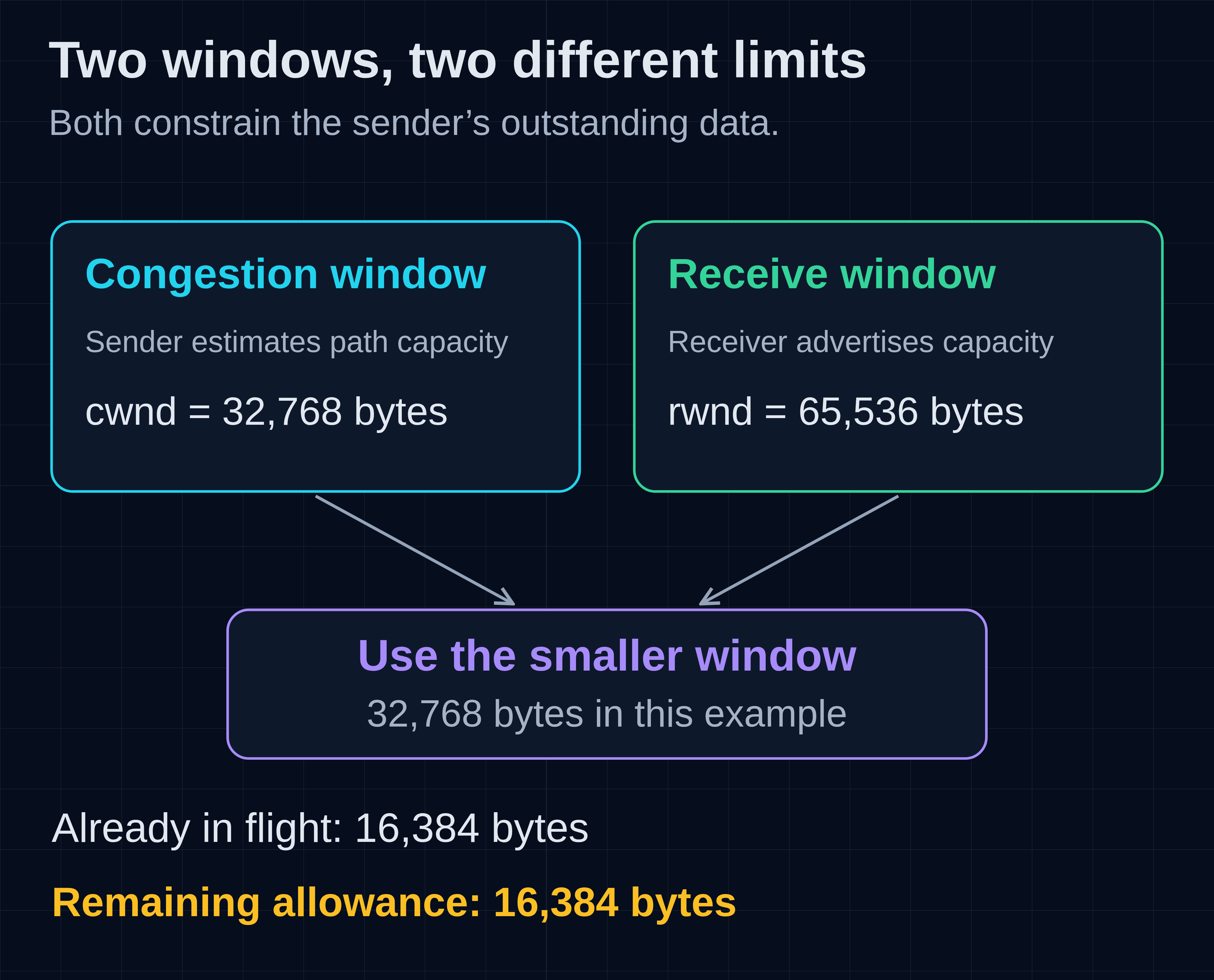
Figure 4. Two independent constraints on one sender. The receive window comes from the receiver; the congestion window is maintained at the sender. Values are illustrative, not measurements.
For example, suppose rwnd is 65,536 bytes, cwnd is 32,768 bytes and 16,384 bytes are already in flight. The simplified model leaves room for another 16,384 bytes. Increasing the receive buffer would not remove the current congestion-window limit. Large advertised receive windows use TCP's window-scaling extension, which allows the header's 16-bit window field to represent a larger value.[3]
Classic slow start increases the congestion window rapidly as acknowledgements arrive, rather than assuming the full path capacity is available immediately. Congestion avoidance then probes more cautiously, and loss or congestion indications change sending behaviour. The exact growth and reduction rules depend on the algorithm: CUBIC, for example, uses a cubic growth function rather than merely reproducing Reno's linear congestion-avoidance behaviour.[16][17]
Loss is evidence an algorithm reacts to, not an infallible diagnosis of congestion. Reordering, link problems and other failures also matter. Conversely, a path can suffer long queues and high latency without dropping every burst. Looking only at packet loss misses part of the performance story.[16][17]
RTT makes the feedback loop tangible. At an illustrative 100 megabits per second and 40 milliseconds round-trip time, roughly 500,000 bytes must be in flight to sustain that rate in an idealized steady state. This bandwidth-delay product describes an idealized steady state; application limits, headers, congestion, loss and competing traffic can all reduce useful throughput. A fast link with a small effective window can still deliver a slow transfer.
Why use UDP if TCP handles reliability?
UDP provides datagrams rather than an ordered byte stream. It preserves the datagram abstraction but does not itself provide TCP's retransmission, ordering, duplicate protection or congestion-control machinery. Applications can choose different trade-offs or build a richer transport on top; UDP does not mean the complete application must be unreliable.[18]
For some communication, a late result is less useful than a current one. For other protocols, independently framed messages are a better starting point than a single ordered stream. These trade-offs concern message delivery as well as speed. A UDP-based application still needs appropriate behaviour under loss and congestion.
QUIC is the important web example. It runs over UDP and provides reliable ordered streams, flow control, connection management and integrated security, with loss recovery and congestion control specified as part of the transport design. HTTP/3 uses these capabilities rather than assuming a TCP connection underneath.[19][4]
QUIC's independent streams avoid TCP's transport-level head-of-line blocking between streams: a gap in one stream need not prevent delivery on another. A stream still has its own ordering requirements, a lost packet can contain data from several streams, and the connection still shares network constraints.[19]
What do NAT, firewalls and proxies change?
Routing chooses where a packet goes next. Network Address Translation changes addresses and sometimes ports. A firewall applies traffic policy. A transport-terminating proxy creates separate transport conversations. These functions can live on one device while serving distinct roles.
The IPv4 gateway translation introduced earlier changes what each endpoint observes. If we add NAPT to the original path, the server sees the translated source address and port rather than the client's original pair. Replies depend on the gateway retaining the matching translation state.[20]
That distinction matters when comparing observations. A client-side socket, a NAT mapping and a server-side socket can describe the same conversation with different endpoint values. A NAT-related resource limit can prevent new connections even while existing ones continue. But a translation table is not, by itself, a complete description of firewall policy: permitting or denying traffic is a separate decision.
A proxy that terminates TCP goes further. The client talks to the proxy's TCP endpoint, and the proxy opens or reuses another connection toward a backend. Each connection has its own sequence numbers, windows and lifecycle. An ACK from the proxy's client-facing TCP therefore does not establish that the backend has received the request. The acknowledgement covers the client-to-proxy connection.[3]
Addresses and packets now have context. The remaining question is how to use that context when the visible symptom is simply “the request failed.”
What can local observations actually tell us?
Observe the boundary that matches the symptom. Name resolution, route selection, connection establishment, TLS negotiation and application processing are different stages. A successful check at one stage narrows the investigation; it does not establish that every later stage succeeded.
On Linux, ss can show TCP sockets and, where the networking environment exposes them, internal TCP information. Use a filter for your own test's port rather than collecting unrelated connections.[21]
In a separate bounded loopback check, the server listened on port 49419 and the client used port 26460. While both sockets were open, this command was run in the same networking environment:
ss -tin '( sport = :49419 or dport = :49419 )'
The relevant rows were:
ESTAB 0      0          127.0.0.1:26460    127.0.0.1:49419 reordering:0
ESTAB 0      0          127.0.0.1:49419    127.0.0.1:26460 reordering:0
These are two endpoint views of one connection, not two connections initiated independently. The local and peer addresses reverse. Substitute your own test's current port: these particular sockets were closed after inspection. The short stream.py example finishes too quickly to reliably inspect interactively.
The available TCP diagnostics depend on the host and networking environment; some environments expose basic socket rows without the richer information requested by -i.
A route lookup asks a different question:
ip route get 127.0.0.1
The observed output was:
127.0.0.1 dev lo src 127.0.0.1
    cache
ip route get performs a route lookup without sending a packet. Here the selected device is the loopback interface, lo. It does not exercise Ethernet, ARP, an external router or the path in Figure 1.[22]
For a request to a real service, the same layered reasoning gives more useful questions than “is the network working?”:
- Name resolution fails: was an address obtained at all? No TCP connection to that resolved destination has yet been established.
- Connection is refused: the attempt was rejected, commonly because no listener accepts that address and port or policy actively rejects it. That is different from receiving no response.
- Connection times out: investigate the selected destination, routes, filtering and return traffic; silence does not identify which device dropped a packet.
- TLS fails after TCP connects: examine the secure-channel negotiation and identity checks rather than treating an established TCP connection as proof of a valid TLS session.
- The server returns an HTTP error: transport carried a response. The error's meaning belongs to HTTP and the application; it is not equivalent to a failed handshake.
Local socket limits, ephemeral-port availability and application deadlines also affect connection attempts. Some connect() failures occur locally, before any packet is sent.
How does a TCP connection end?
An orderly close finishes each direction separately using FIN and acknowledgements. A reset, RST, aborts a connection instead. TIME_WAIT retains state after an active close to handle delayed traffic and final-acknowledgement reliability; it is not, by itself, evidence of a leak.[3]
FIN follows the bytes already sent in that direction. The receiver can read those bytes before observing end-of-stream. The other direction can continue, as the Python example demonstrated. An application expecting a response can keep receiving after it has finished sending.[3][13]
The familiar drawing with four separate close packets is only one arrangement. Acknowledgements and FINs can be combined, and simultaneous close is possible. Applications also have different close and abort behaviour. A reset aborts the connection rather than completing the application exchange.[3]
The endpoint performing the active close normally enters TIME_WAIT. Its purpose includes keeping old duplicate segments from being confused with a later incarnation of the connection and allowing the final acknowledgement to be sent again if needed. TIME_WAIT duration and safe reuse behaviour have implementation-specific details. Tuning these values requires accounting for connection lifetimes and delayed segments to preserve safe reuse.[3]
This returns us to the original request. Delivering packets, reconstructing bytes, accepting an application request and committing its effects are distinct events. Understanding those boundaries explains both why everyday communication works so well and why no single “connection successful” signal can prove the whole operation succeeded.
Frequently asked questions
Does a TCP acknowledgement mean the request succeeded?
No. It acknowledges bytes at the receiving TCP endpoint, not application processing or durable effects. The application needs its own response semantics. If the response is lost, retrying safely may require idempotency or another way to determine the original operation's outcome.[3]
Can TCP deliver the same application operation twice?
TCP uses sequence numbers to prevent retransmitted bytes from appearing twice in one delivered stream. An application can nevertheless submit the same operation again, for example on a new connection after a timeout. Transport-level duplicate handling does not provide exactly-once business operations.[3]
Why can a small request work while a larger transfer stalls?
An MTU problem is one possibility: small packets pass, larger ones do not, and required feedback fails to reach the sender. Receive-window limits, congestion and application behaviour are other possibilities. A larger transfer can expose constraints that a small request does not encounter.[3][11][12]
Is this networking knowledge only useful for infrastructure work?
No. Stream framing affects application code; acknowledgement boundaries affect API retries; latency and windows affect perceived responsiveness. Infrastructure operations are one use of the model, alongside software design, performance analysis and understanding the technologies behind everyday tools.
Sources
- Internet Society: A Brief History of the Internet
- RFC 1122: Requirements for Internet Hosts — Communication Layers
- RFC 9293: Transmission Control Protocol
- RFC 9114: HTTP/3
- RFC 4632: Classless Inter-domain Routing
- RFC 826: Ethernet Address Resolution Protocol
- RFC 4861: Neighbor Discovery for IP version 6
- RFC 8200: Internet Protocol, Version 6 Specification
- RFC 791: Internet Protocol
- RFC 1191: Path MTU Discovery
- RFC 8201: Path MTU Discovery for IP version 6
- RFC 4821: Packetization Layer Path MTU Discovery
- Python documentation: socket — Low-level networking interface
- RFC 2018: TCP Selective Acknowledgment Options
- RFC 6298: Computing TCP’s Retransmission Timer
- RFC 5681: TCP Congestion Control
- RFC 9438: CUBIC for Fast and Long-Distance Networks
- RFC 768: User Datagram Protocol
- RFC 9000: QUIC — A UDP-Based Multiplexed and Secure Transport
- RFC 3022: Traditional IP Network Address Translator
- ss(8): investigate sockets
- ip-route(8): routing table management
- RFC 1883: Internet Protocol, Version 6 (1995)
- RFC 4291: IPv6 Addressing Architecture
- RFC 1918: Address Allocation for Private Internets
- RFC 4193: Unique Local IPv6 Unicast Addresses
- IANA: IPv4 Special-Purpose Address Registry
- IANA: IPv6 Special-Purpose Address Registry
- RFC 2131: Dynamic Host Configuration Protocol
- RFC 4862: IPv6 Stateless Address Autoconfiguration
- RFC 1034: Domain Names — Concepts and Facilities
- RFC 4864: Local Network Protection for IPv6
- RFC 6598: Shared Address Space for Service Providers
- RFC 2474: Differentiated Services Field
- RFC 3168: Explicit Congestion Notification to IP
- RFC 6864: Updated Specification of the IPv4 ID Field
- IANA: TCP Parameters — TCP Header Flags
- RFC 9768: More Accurate Explicit Congestion Notification Feedback in TCP
- RFC 7323: TCP Extensions for High Performance
Frequently asked questions
What is TCP/IP and what does it do?
TCP/IP is a protocol suite that provides addressing, routing, and reliable transport. IP handles addressing and packet delivery, while TCP ensures reliable, ordered byte streams between endpoints.
How does TCP ensure reliable data transmission?
TCP uses sequence numbers, acknowledgements, and retransmissions to ensure reliable data delivery. It detects missing data, retransmits it when necessary, and maintains byte order for applications.
Why are IP addresses important in networking?
IP addresses uniquely identify network interfaces and enable data to be sent across different networks. They allow routers to forward packets to the correct destination without understanding the application.
What is the difference between IPv4 and IPv6?
IPv4 uses 32-bit addresses, while IPv6 uses 128-bit addresses, providing a larger address space. IPv6 also has a fixed header size, no header checksum, and uses extension headers for optional data.
How does TCP handle packet loss?
TCP detects packet loss through missing acknowledgements and retransmits the lost data. It uses a retransmission timeout and duplicate acknowledgements to manage recovery, ensuring data integrity.
What role does DNS play in TCP/IP communication?
DNS translates human-readable domain names into IP addresses, allowing applications to locate servers. It doesn't assign addresses or establish connections but helps direct requests to the right destination.
About the author
- I’m a hands-on technology architect, engineer and founder of Turing Technology Services, with nearly two decades of experience in software engineering, platform engineering, site reliability engineering and cloud infrastructure. My work combines architecture and implementation with technical leadership, coaching and helping organisations adopt new engineering practices. I’ve worked with organisations including Shell, ING, ABN AMRO, Rabobank, Schiphol Group and Ahold Delhaize, across complex and regulated enterprise environments. On this blog, I share practical guides and perspectives on software architecture, cloud platforms, reliability and AI, explaining the reasoning behind technical choices as well as how to implement them.
Foundation
Core concepts and practical introductions to software, cloud and platform engineering. Understand the fundamentals, why they matter and how they fit together.